|
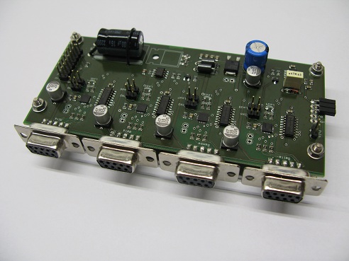
When needing multiple encoder inputs in the same location of the machine, a possible solution is using the 4-input board. Similarly to the single-input board, it is of compact design but can read four 5V line-driver type encoders simultaneously.
Thanks to its built-in voltage regulator, the power supply is stable even in systems comprising a high number of axes. Also, having 4 dedicated microcontrollers, its speed and flexibility are unchanged. The interpolation is set at 4x, te maximum attainable from a square wave encoder. This way, for example, a 3600 pulse per rotation encoder can reach a final resolution of 14400 pulses per rotation. A "latch" digital input, in common between all 4 inputs, allows the board to "freeze" the values of the encoders, values that are then saved in dedicated memory cells whie the board keeps counting the pulsas. This functionality, and the corresponding software commands for reading the memory, are indispensable when using these boards on a measurement machine. The position of all of the encoders are read simultaneously with a maximum temporal error of less than a microsecond. The board features 4 digital inputs for auxiliary buttons, 4 outputs for status LEDs and multiple circuits for running diagnostics on all of the encoder's signals. Using these circuits, of the signals can be checked, thus finding possible malfunctions of the encoder or, more simply, disconnected wires.
This board features an anti-rebound circuit for conditioning a button's input. This is normally used on the "point measurement" button on measurement machines. This circuit ensures that all of the encoder boards memorize the encoder count in the same moment and also avoids duplicated readings of the same point.
|



 Back to Square Wave Boards